The future
outlet
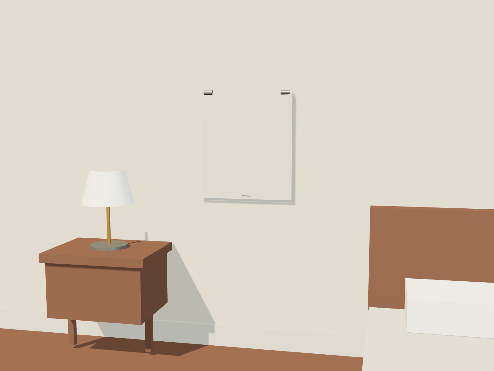
A quiet panel in the bedroom wall. Behind it, a house that can keep changing.
Bury the backbone. Bring the connections to the surface only where life needs them.
Power and data travel through concealed, deliberately accessible routes. At each room, they meet an endpoint with the composed appearance of a small paneled enclosure: a narrow reveal, a finish that belongs to the room, and a cover that closes almost against the wall. Behind that cover are the useful things—an electrical outlet, an Ethernet jack, perhaps a fiber port—and space for the next generation of equipment.
This is a service junction for the room. It borrows the orderly enclosure of a breaker panel, but its purpose is connection, conversion, and renewal. One or two local protective devices could be an option in an appropriately engineered variant; they do not define the object.
The cover brings the wall to life
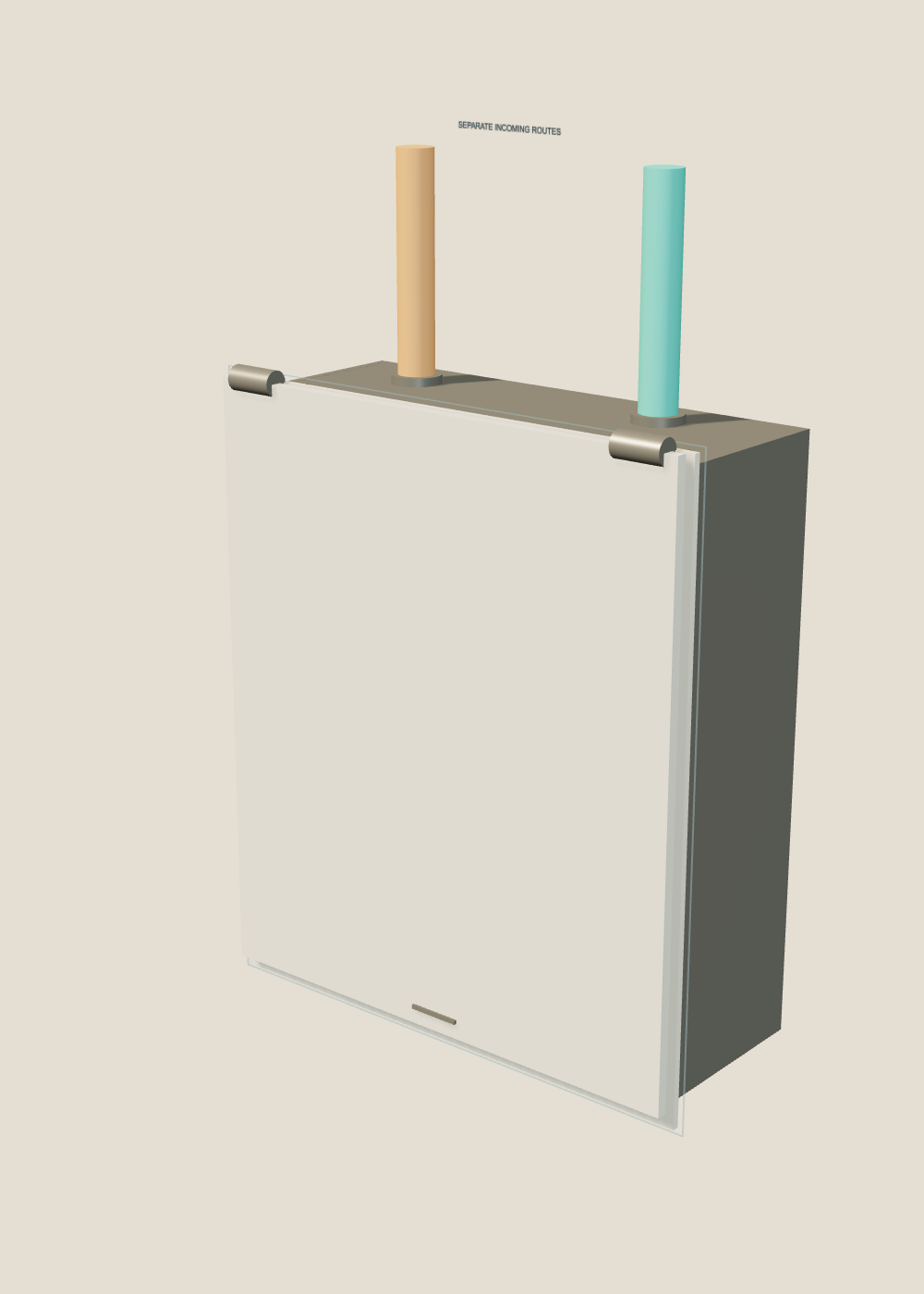
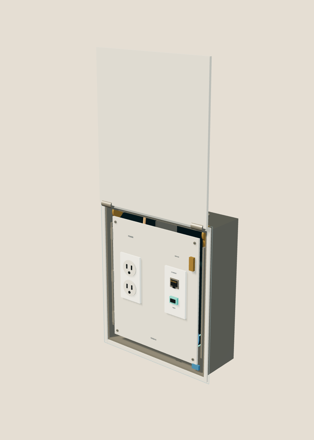
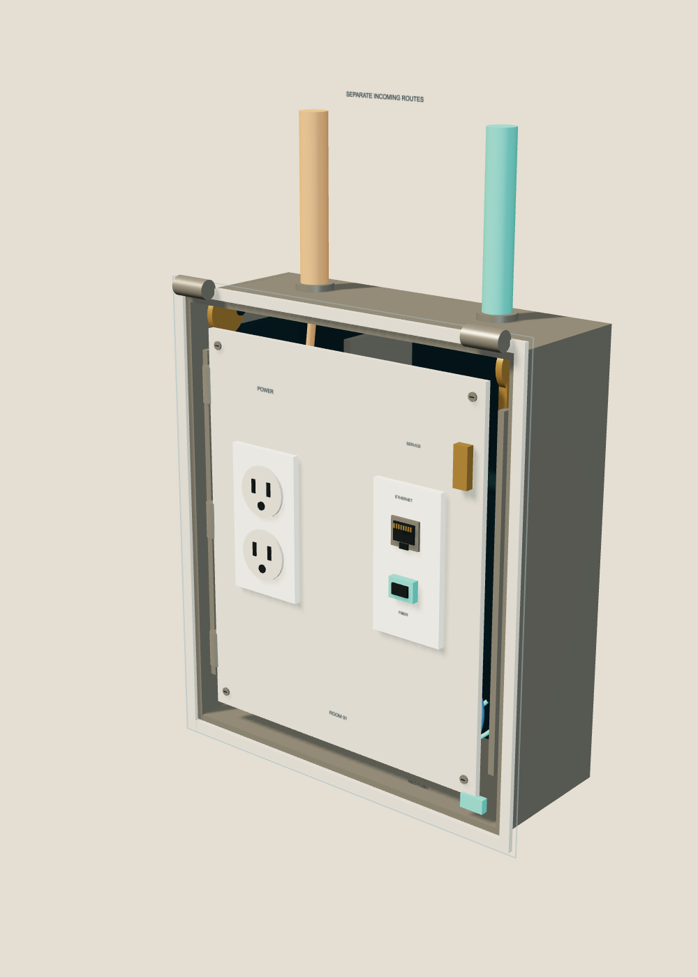
The lid operates the presentation of the connections, rather than merely hiding them. Close it and the carriage retreats; lift it and the face returns to the wall. The proposed coupling uses cover-driven cams and guided translation so the sockets keep facing the room throughout the movement.
The hold-open latch is independent of that coupling. With the face latched forward, the cover can come off its hinge without carrying the sockets away. Refit the cover and release the hold latch to restore the concealed mode. The illustrated closed state assumes plugs have been removed; a future cord-exit variant would need its own clearance and pinch protection.
Open it. Hold it. Get behind it.
Lift the cover all the way, engage the flush latch, then release the separate service latch. The gold latch opens the inner leaf; the blue one holds the carriage at the wall. Drag the model to inspect the mechanism, or choose a camera view.
All five still images and the interactive assembly use the same authored 3D model. The housing is illustrated at 360 × 420 × 140 mm, with 40 mm of face travel. These are concept proportions, not installation dimensions. The animation prescribes the intended movement; it does not establish a working cam profile.
The second opening is for the future
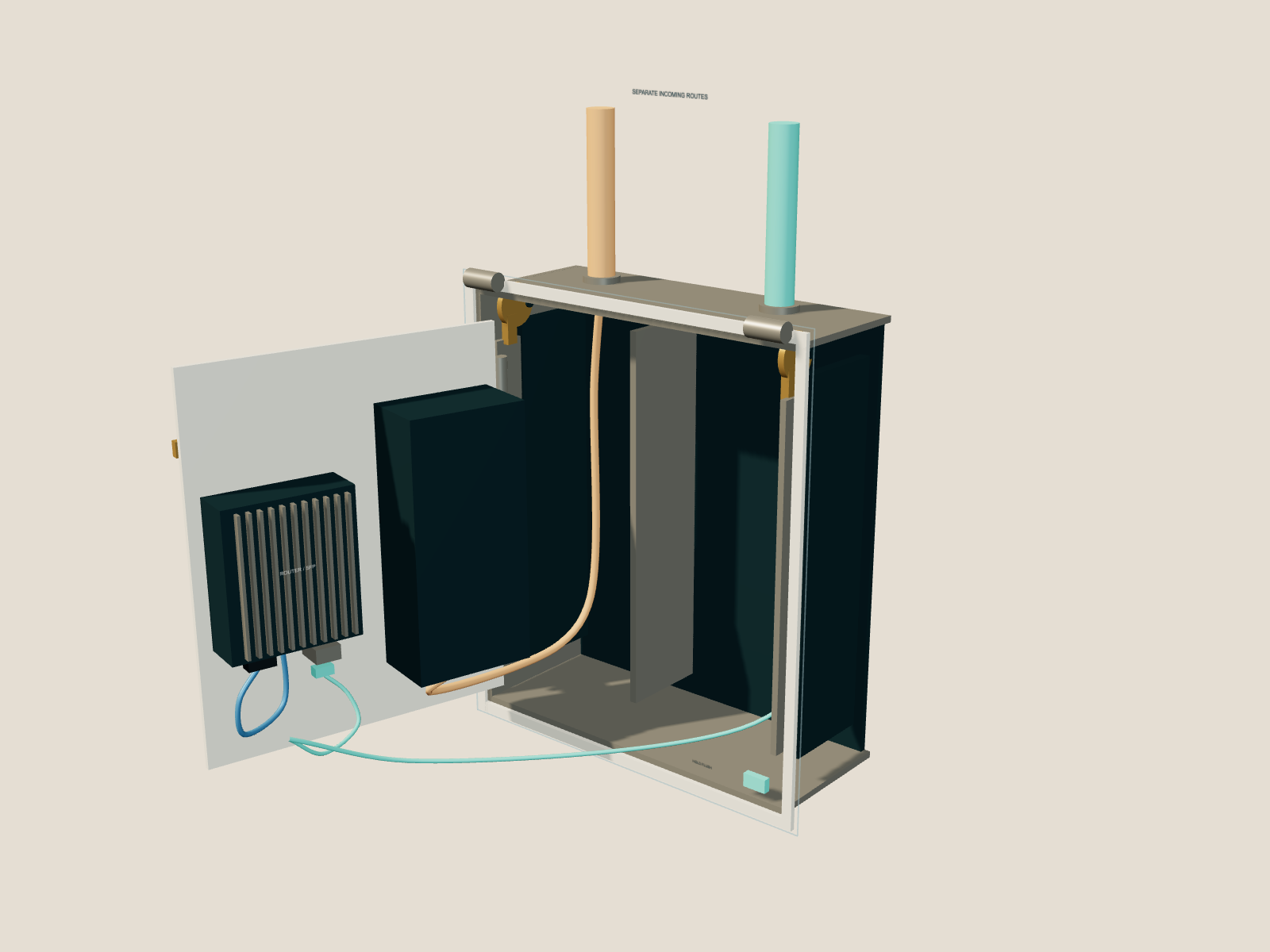
Release the inner latch and the whole service leaf swings outward. Now the back of the ports, the cartridge mount, and the cable connections are reachable. The wall opening becomes a place to work, rather than a hole to fish through.
In this version, a compact wired router rides behind the data side of the face. Fiber reaches an SFP optical module. A short internal Ethernet patch lead connects the router’s single copper network port to the jack immediately in front of it. An optional front fiber coupler gives the room direct optical access.
The silver fins mark the replaceable communications cartridge. The dark pod on the other side keeps the power components enclosed when the leaf opens. The cutaway removes one housing side to show the separated incoming routes and the space reserved for flexible service loops.
Let the building last longer than its interfaces
room enclosure
and room-facing ports
The buried part should be a durable system of routes and reachable junctions. The part that becomes obsolete should be the easiest part to remove. A router, optical transceiver, connector standard, or room function can change while the surrounding plaster, the enclosure, and compatible backbone cables remain in place.
That is the useful sense of “rewiring without changing the wiring”: change what the existing backbone does by replacing its endpoints. It is not a promise that a cable will never need replacement. If a future system needs different cable, an accessible conduit route and deliberate pulling access offer another kind of continuity—replacement without opening the finished wall along its length.
A bedroom might begin with power and one wired connection. Later the same opening could receive a different optical interface, a new network cartridge, or a simpler passive termination. The room keeps its architecture while the small machinery at its edge moves forward.
What the enclosure still has to earn
A convincing mechanism must do more than reach its illustrated positions. The cover needs a realizable cam or linkage, a stable hold-open action, and a detachable hinge that cannot release accidentally. The leaf needs enough service clearance, strain relief, and controlled cable loops to move repeatedly without loading its connectors or overbending its fiber.
The shared outer enclosure also needs engineered separation between mains power and communications, suitable protective measures, and a heat path for active equipment when the cover is shut. A metal cavity may be a poor home for a Wi-Fi antenna; the example uses a wired router. Enclosure depth, wall construction, service access, and the applicable product and installation requirements determine whether this form can become a practical bedroom fitting.
Existing divided device boxes demonstrate power and low-voltage services at one point of use; optical transceivers already connect fiber networks to electronic equipment. The proposal is to unite those ingredients with a moving, maintainable room interface. The model shows that intended arrangement, not a tested or certified product.
A house should not have to become a construction site every time its connections grow up.
Technical references: Legrand divided point-of-use box; Ubiquiti optical transceiver overview. These support the component principles, not this enclosure’s engineering.