Space Elevator
A plan to get man a vacation on the Moon.
Give each part of the climb its own machine.
A mountain can carry a foundation. A pressurized skin can hold a shape. Rotors and balloons can support a structure in air. A rotating tether can exchange momentum with a spacecraft. The proposition is to join those abilities into a route: an ascent from Medellín, an appointment with a moving cable, an orbital transfer, and a return through an enormous system of pressure cushions.
The atmosphere and the orbital system have different jobs. The lower structure brings the car to a launch point. The upper tether comes to meet it. They connect through a timed handoff; the orbital station does not stand motionless above the city.
Meet the machine from the ground upward. Build its upper transport first, then work downward toward the ground connection. The passenger’s route and the construction sequence run in opposite directions.
Two journeys through the same sky
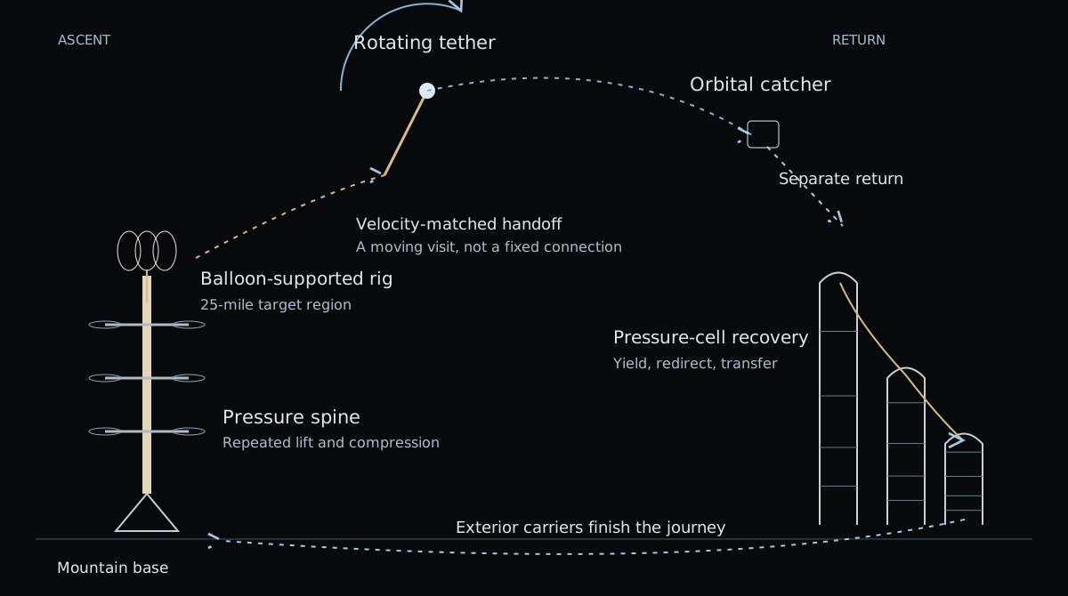
The physical connections are the subject of this diagram. Horizontal distance, component size and support-station spacing are schematic. The orbital tip meets the lower route intermittently.
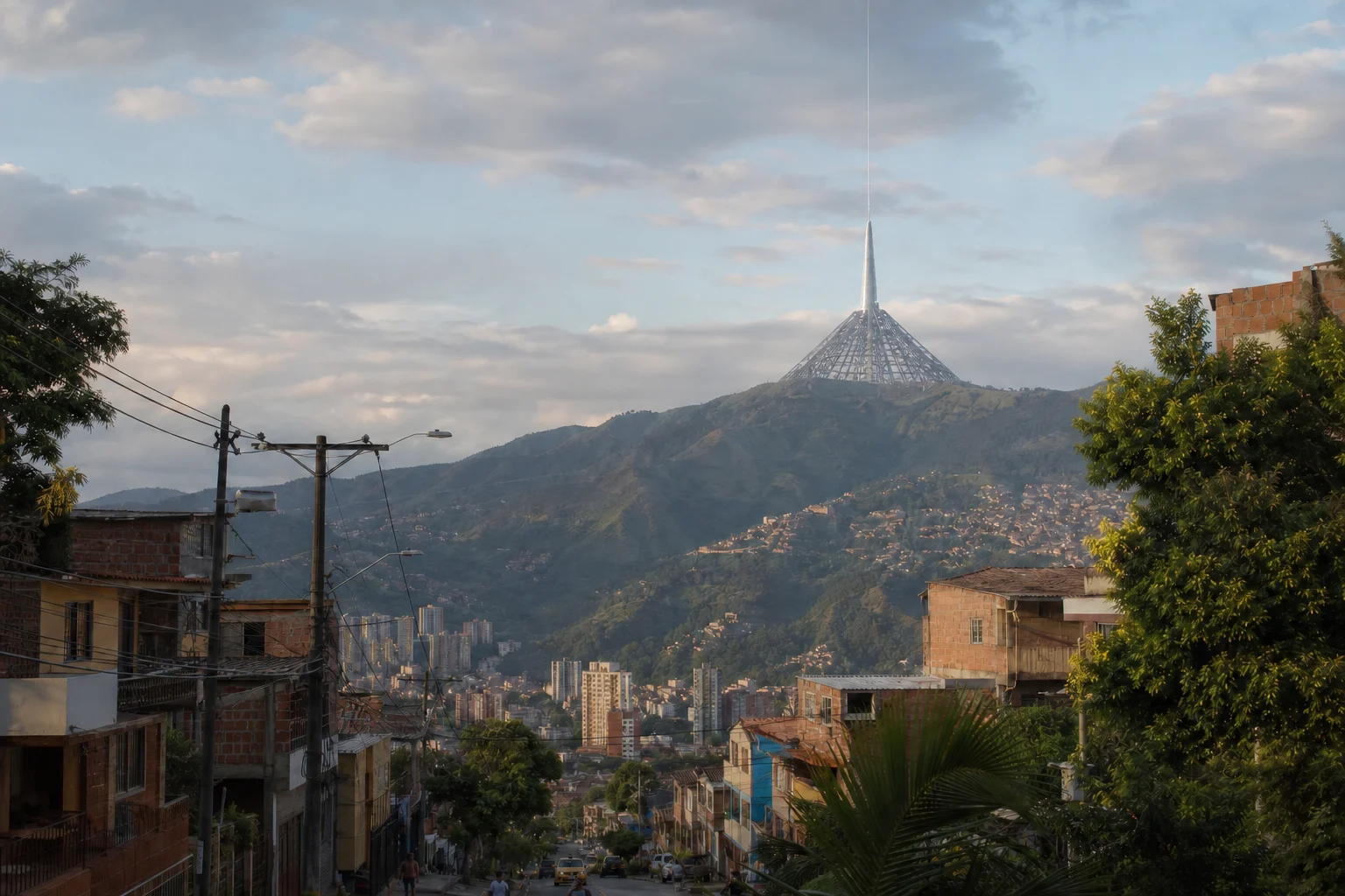
Medellín, first
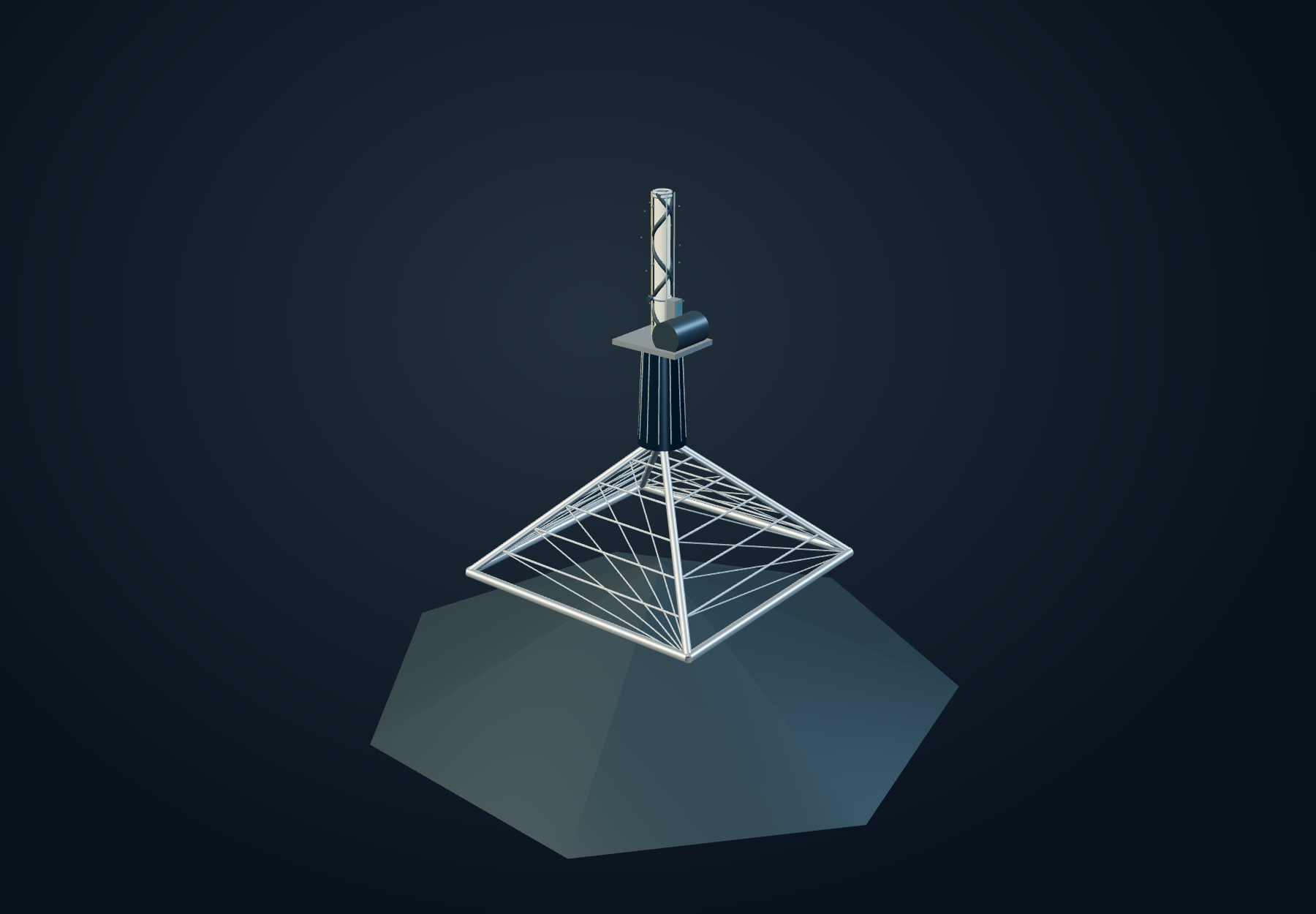
The view begins in the city and ends somewhere above the mountains. A vast hollow pyramid spreads the foundation across a summit. Its crown carries the broad skyscraper, then the derrick and compressor house from which the pressure spine rises.
The scale is deliberately metropolitan: a manufactured mountain with machinery at its crown. The hollow framework provides a way to picture the structural route from summit equipment to foundations, rather than treating the whole pyramid as a solid block.
Medellín lies about 6.24° north of the equator. An orbit visiting it must have adequate inclination, and each visit has a ground track and a time. The city remains the proposed location; the rendezvous must be designed around its actual latitude.
The pressure spine
The central tube is woven Kevlar supported by two reinforced carbon-fiber ribs, one spiraling clockwise and the other counterclockwise. The crossing helices give the skin a structure around which to hold its form. Large one-way flaps admit air from below; compressors replenish the successive sections.
Yes, it is a giant pneumatic erection. The useful part of the comparison is that pressure and tension hold up a shape that would otherwise fold. The engineering question begins with where that tension goes: into the ribs, seams, collars, stations and foundations.
Power conduits climb beside the tube. The conventional passenger carriers stay outside, on their own vertical wires. Keeping that path visible matters: a traveler does not have to pass through an air valve to reach the next platform.
Turn the parts in your hands.
Open the pressure spine, move its flap, inspect the rotor supports, or close Otto’s catcher arms. Each component is an actual 3D assembly. The still illustrations throughout the page are views of these same objects.
Pressure holds a shape. The stations carry a load.
A pressurized tube behaves like a tensioned membrane. In a thin circular wall, circumferential stress scales with pressure difference times radius divided by skin thickness. The pressure also pushes on the closed ends. Those are internal loads with a structural return path; a sealed chamber does not acquire free external lift merely because its pressure rises.
That distinction gives the flying stations their role. They introduce external lift along the spine, while the ground supplies a foundation and the skin carries membrane tension. Air itself adds mass. A larger tube buys interior space and a larger pressure resultant while demanding more material, more gas and a larger wind-facing area.
Inspect one pressure cell
Enable JavaScript to inspect the membrane balance. These are local pressure-vessel equations, not a whole-tower stability model.
A chain of flying stations
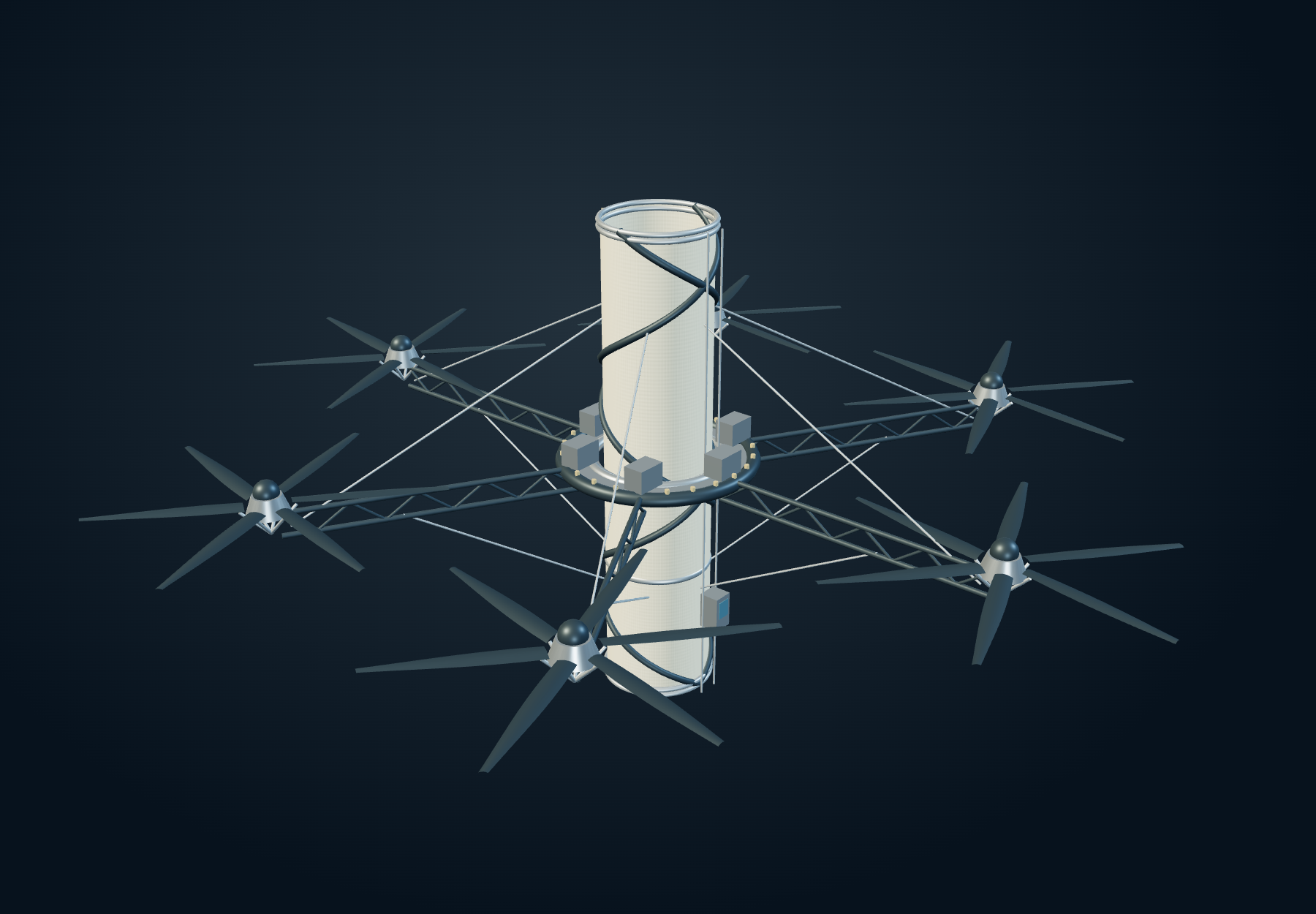
A platform clasps the tube like an annular deck. Slender trussed booms spread the rotors away from the skin, and stays connect the outer assembly to collars above and below. Each station supplies lift, controls its local position and powers another compressor.
No single rotor carries the whole route. Sharing support reduces the unsupported span, but the stations remain coupled by the tube, electrical conductors and the moving load. Wind on one section reaches its neighbors through those connections.
The model makes the geometry inspectable: six rotor disks have room to turn, their booms meet the platform, and the suspension lines terminate at collars. Their diameters, spacing and power remain design variables.
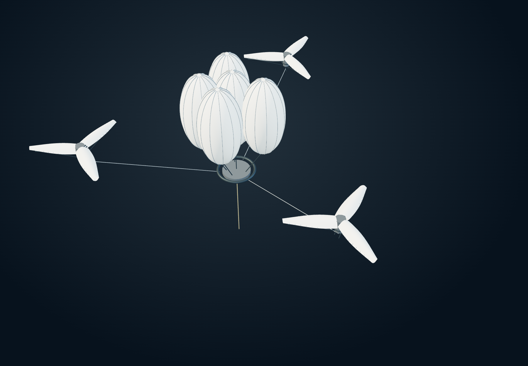
The air thins. The machine changes.
At the upper end of the pressure spine, the broad tube gives way to slender tension lines. Above it, a balloon cluster and three outboard heli-blimps support and position the rig. The three machines sit around it at 120-degree bearings; the intended vertical support comes from their upward force components, while their horizontal pulls balance.
The target region is roughly twenty-five miles up—about 40 km. There is still air here, but very little of it. Scientific balloons do reach this regime: NASA’s XL-Calibur description places its balloon-borne observatory near 40 km. Carrying a scientific gondola and sustaining this transport structure are different scale problems.
How much atmosphere is left to work with?
Move the altitude while keeping the load and rotor area fixed. Rotor power rises as the air gets thinner, while the lift available from a fixed balloon volume falls. The calculation uses the lower-atmosphere layers of the U.S. Standard Atmosphere, 1976.
Air, disk area and supported mass
Enable JavaScript to inspect the atmosphere, ideal rotor-power and helium-buoyancy estimates.
Ideal hover uses P = T√(T / 2ρA), the actuator-disk momentum balance. NASA’s NDARC theory report develops rotor performance beyond this lower-bound relation.
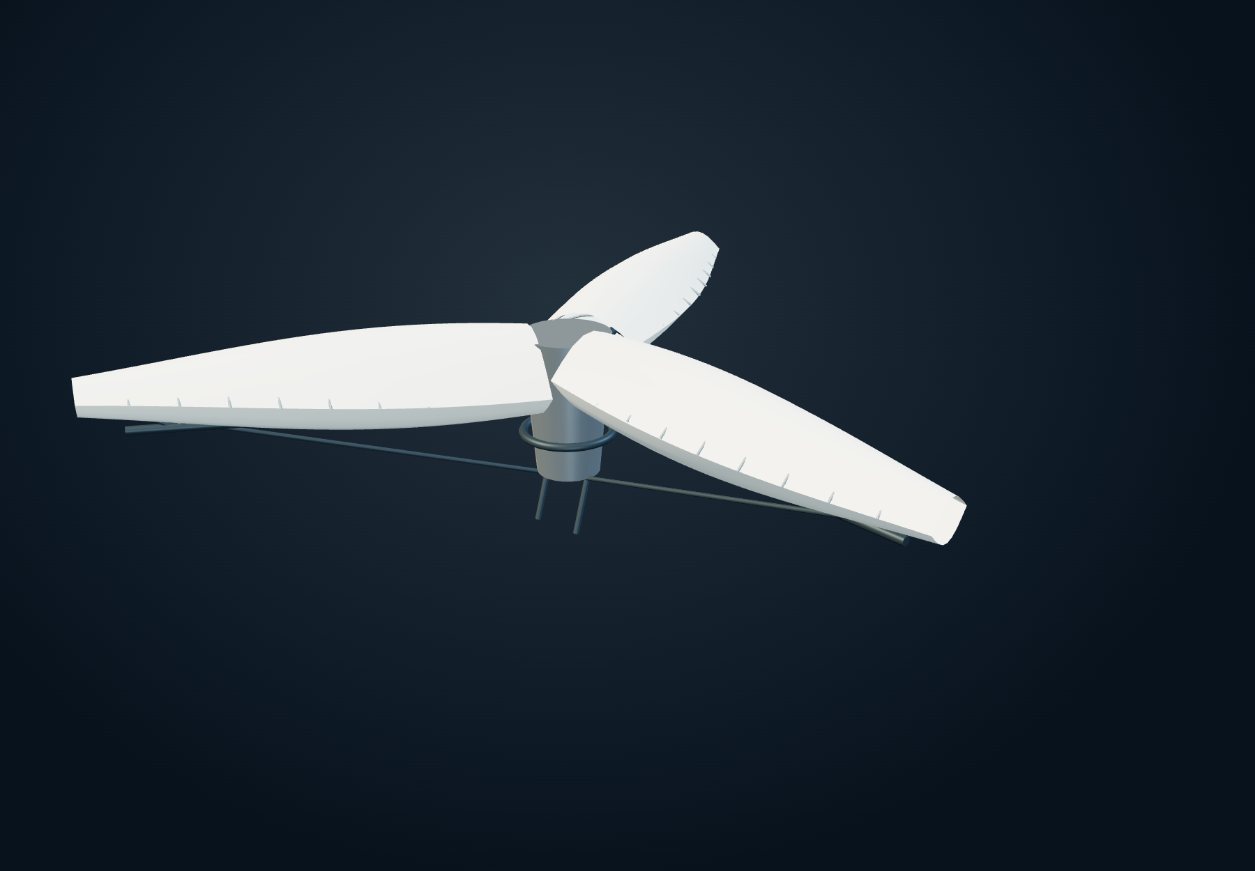
The heli-blimp is mostly wing.
These are robotic high-altitude machines with vast inflated wing segments and exceptionally light carbon-fiber supports. The fabric supplies an aerodynamic surface; ribs and stays give that surface a defined relationship to the hub. The point of the volume is to obtain area without turning every square metre into a heavy rigid blade.
The power proposal remains open: electrical supply, hydrogen and oxygen delivered through lines from below, or a compact reactor stationed far from the occupied route. Each option brings its own mass, cooling and supply problem. Moving the source does not remove the power demand at the rotor.
The three machines must hold a common rig while responding to weather and one another. Their control task includes keeping the transport line within its usable geometry, not simply maintaining three independent hover points.
Otto must arrive with the right motion.
The car is two tonnes of elevator plus eight tonnes of passengers, cargo, thrusters, balloons and other systems. It accelerates along the upper route, leaves the lower guide and meets the orbital tether at an appointed place and time.
Altitude is only half the rendezvous. A car going rapidly upward and a cable tip moving sideways can have identical speed readings and still meet violently. Their positions, directions and velocities must coincide. Small thrusters trim a residual; they do not quietly supply the whole climb to orbital speed.
Timing also constrains the acceleration story. Starting from rest and reaching 4,870 mph in two minutes at constant acceleration covers about 131 km, not the roughly 362 km between 25 and 250 miles altitude. The launch point, acceleration history and coast must therefore be specified together. The simulator begins at the proposed capture location; it does not invent a solved lower ascent.
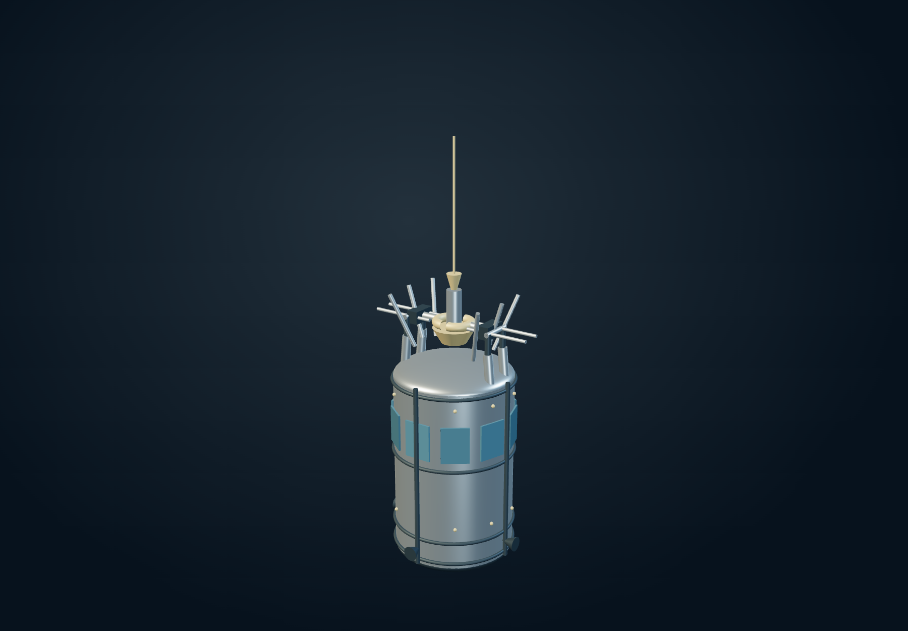
The moving appointment
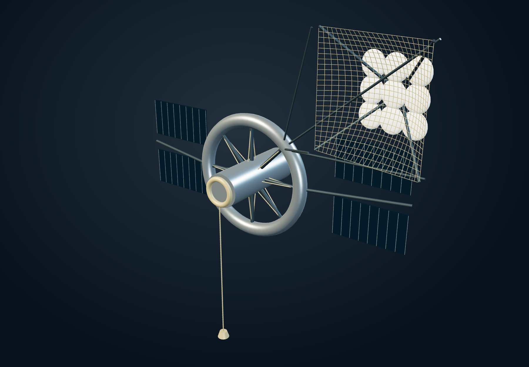
The orbital hub races forward. Its cable rotates so that the bottom tip sweeps backward relative to the hub. Those velocities subtract. A hub moving at roughly 17,000 mph and a tip sweeping backward at 12,000 mph produce a tip moving forward at roughly 5,000 mph.
That is the useful trick. The upper transport comes down with a reduced forward velocity, allowing a much slower vehicle to meet it. A headed terminal enters Otto’s open receiver. Opposed jaws close around the narrower neck, leaving the wider shoulder below them. As tension comes on, the shoulder bears beneath the jaws and a short carriage takes up the remaining movement. The surrounding load frame transfers that force around the occupied cabin.
Velocity matching is one condition for capture. The subsequent curved path also demands acceleration. A smooth arrival does not make the rest of the swing gentle.
Receive. Retain. Take up the load.
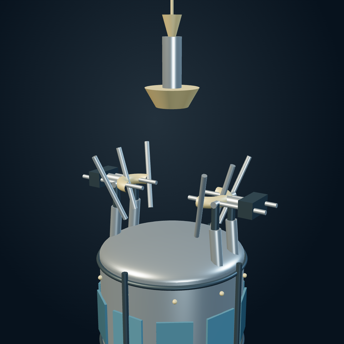
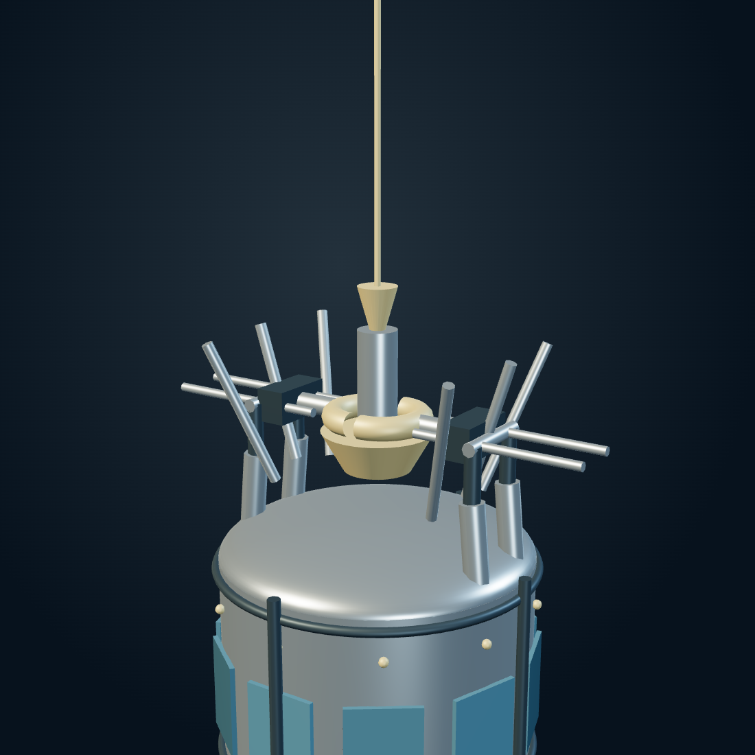
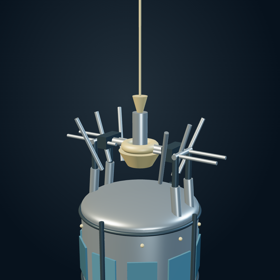
The model shows a possible retaining geometry and its sequence. Guide clearances, closing speed, carriage stroke and damping have not been specified; the orbital model supplies the approach mismatch they must accommodate.
Make the appointment.
The hub follows a circular Earth orbit and the tether rotates at the entered relative tip speed. Start with the proposed dimensions, scrub the swing, and compare Otto’s velocity with the tip. “Match velocity” aligns both velocity components at the lowest point; it does not validate a capture mechanism.
Orbit, rotation and the handoff
Enable JavaScript to inspect the numerical model. The article describes the mechanism without it.
The gold tip follows a prescribed rigid-tether path, assuming attachment after capture. After the selected release angle, Otto follows a free two-body trajectory. “Free Otto” follows a separate two-body trajectory from the same initial position. Hub recoil, tether elasticity, atmosphere, control dynamics and docking compliance are omitted. All velocities use one Earth-centered inertial frame; surface-relative launch data require Earth-rotation correction. One model tonne is 1,000 kg. Playback runs at 8× elapsed time.
A cable that carries motion
The proposed upper line uses protected Zylon HM, with reinforcement beyond the ordinary fiber as an avenue for development. The familiar one-inch diameter and roughly two-hundred-tonne mass are a way to picture its scale. The more demanding question is the tension needed to carry its own rotating mass and the attached car.
Toyobo’s Zylon technical data give 5.8 GPa fiber tensile strength and 1.56 g/cm³ density for HM. Those fiber properties are useful screening inputs, not a finished long-cable allowable. Protection, splices, creep, environmental exposure and a working margin consume performance.
At the proposed spin speed, making a uniform cable thicker adds both area and rotating mass. It does not eliminate the self-stress term. A taper changes the distribution; slowing the tip changes the rendezvous. Material, geometry and motion have to be solved together.
The orbital instrument supplies this material screening from the same dimensions and rotation speed. At its initial settings, the spin-only uniform-strand self-stress is about 22.4 GPa, already above the cited fiber strength.
The throw and the bill
After capture, the tether carries Otto upward and adds forward motion. Release at a chosen phase establishes a new free trajectory. That trajectory may be bound to Earth or may escape it; release near the upper sweep is not automatically an orbit that meets a nearby station.
The catcher is a second rendezvous. A broad net and yielding cradle can spread a remaining docking impulse over distance, once the incoming car and receiving station have compatible trajectories. Pillows do not substitute for matching orbital motion.
Every outward transfer changes the momentum and energy of the combined system. Electric propulsion, appropriately scheduled returning cargo and a larger orbital reservoir can help manage the exchange. The mass of the station changes the size of its response, not whether conservation applies.
The family resemblance is real.
Momentum-exchange tethers have a substantial research history. Boeing’s NIAC HASTOL study examined a hypersonic vehicle meeting a rotating tether. NASA’s MXER dynamics report describes the detailed modeling needed for rendezvous, including environmental perturbations and accurate tip prediction.
Those studies support taking the moving-handoff mechanism seriously. The pressure spine, flying stations, balloon rig and recovery towers constitute the additional architecture here. Their connections need their own analysis; the established tether literature does not validate the whole route.
At the receiving station, cargo and passengers transfer into onward transport. The Moon is the destination, not the height of the hub. A cislunar vehicle must still perform the departure, navigation and arrival associated with that next leg.
The baby spider comes home.
The return car leaves on a separate line, with the delicacy of a baby spider releasing a thread. The outbound hook and the return cable need not be the same mechanism. The return line lowers or redirects the car before release, with braking before the end of the line.
After release, its trajectory must intersect a recovery region with a defined entry speed and angle. At roughly a hundred miles up, orbital motion has not ceased to matter. As the car descends, gravitational potential becomes kinetic energy and the atmosphere starts exchanging both momentum and heat with it.
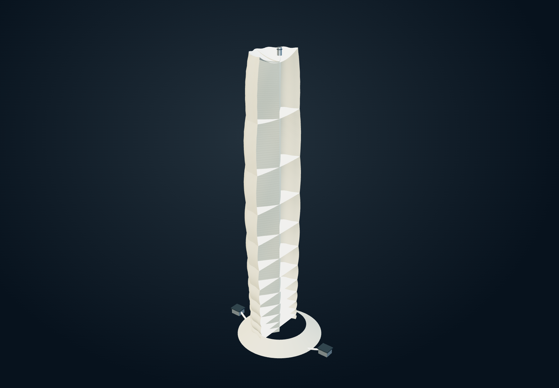
The return concept meets that descent with a structure of extraordinary size: a pressurized Kevlar envelope fifty miles tall and ten miles wide, divided by internal bulwarks. The upper cells are tall; the cells become shorter and denser toward the bottom. Ground turbines replenish the air.
The world’s largest rescue raft
The car enters a yielding system rather than a rigid landing pad. Fabric deflects, pressure cells deform, and displaced air is released or moved. The upper cells shorten and the entry surface forms a depression. Flexible partitions pass force into neighboring fabric while the broad lower skirt anchors the envelope. The compression control shows that change in shape; it is not a fabric-dynamics calculation.
The attraction is distance. Tens of kilometres provide room to do work that a short catcher could only do with a much larger force. The governing quantity is the car’s kinetic energy plus the gravitational work added during the descent.
Volume alone is not a braking law. The envelope must produce a particular force along a particular path while keeping the car coupled to the cushion. The drawing shows the cell arrangement; the calculation below asks how much work that arrangement is being asked to perform.
Spend distance to remove speed
Enable JavaScript to inspect recovery distance, energy removal and mean load.
Turn the fall sideways.
Near twenty miles altitude, the slowed car leaves the first cushion and transfers through a descending chain of smaller towers. Each bends and redirects its path, exchanging further energy while shifting the motion from a fall toward a traverse. The last inflated surface forms a shallow ramp to the pressure-spine platform.
The sequence needs continuity at every crossing: position, direction, speed and a receiving surface ready to take the next load. A gentle final stop cannot cancel a severe earlier pulse. The route must be evaluated as a complete history of the forces transmitted to the car.
At the platform, the extraordinary part ends. People and goods transfer into exterior wire carriers and descend the spine in something recognizably like an elevator.
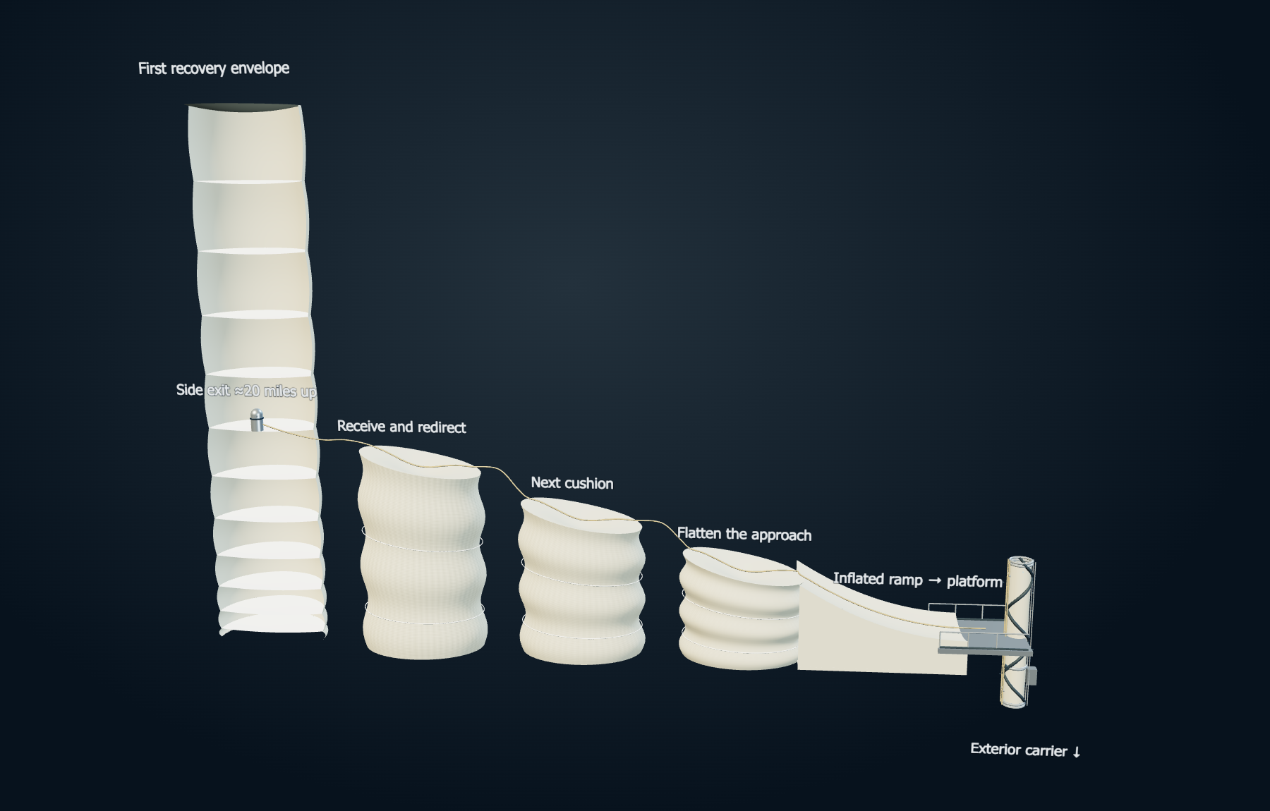
Scrub “Return journey” or run the sequence to follow each crossing and the platform transfer. “Follow cabin” brings the camera alongside the car; switch it off for the whole route. Cabin size, cushion spacing and intermediate heights are schematic. Local yielding is an illustrative deformation; the sequence does not solve contact forces, ballistic crossings or fabric dynamics.
Build downward. Commission every handoff.
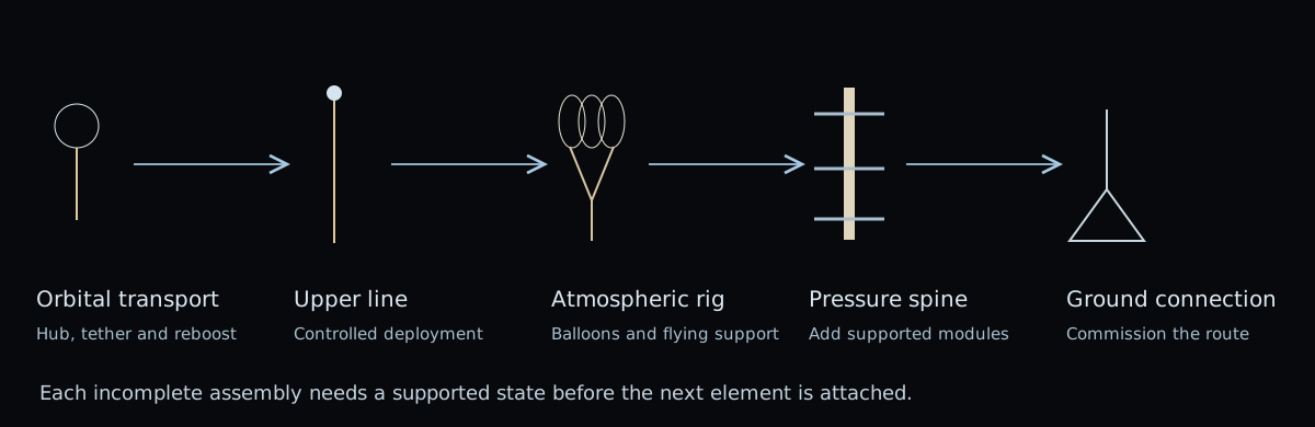
The construction begins with the orbital transport and its deployable tether, then establishes the upper atmospheric rig, the successive spine modules and the ground connection. Each partial assembly needs its own supported state before the next section is added.
The rotating tip is an intermittent visitor during operation. It cannot also be assumed to hold a ground-fixed lower structure continuously. Deployment, temporary supports and the transition into normal service therefore belong in the construction design, alongside the finished route.
What the connected machine has to close
| Connection | The calculation or demonstration that matters |
|---|---|
| Ground → spine → stations | Membrane, rib and collar loads coupled to wind, gas weight, compressor demand and the loss or movement of a support station. |
| Spine → balloon rig → launch | Whole-system mass and power, available rotor thrust and buoyancy, a defined acceleration path, aerodynamic heating and the actual launch state. |
| Otto → rotating tether | A three-dimensional rendezvous, finite capture stroke, a tapered and protected cable, coupled hub recoil, swing acceleration and flexible-body dynamics. |
| Release → catcher → onward transport | A compatible orbit, a bounded residual impulse, a reboost budget and a schedule that accounts for previous transfers. |
| Return → pressure cells → home | Entry trajectory, heat, transient gas flow, fabric deformation, car coupling, the full acceleration history and the transfers between cushions. |
The interactive models isolate useful relationships. Their initial numbers also reveal unfinished parts of the quantitative design: about 9.2 g at tether capture, uniform-strand spin stress above ordinary Zylon’s fiber strength, and about 11.9 g of distance-averaged support load in the illustrated return. These results locate work to do within the architecture; they are not evidence of a passenger-ready system.
A route assembled from useful machines.
The ambition is to make each regime carry the part of the journey it can support: ground structure, tensioned fabric, aerodynamic lift, buoyancy, orbital momentum and a long recovery stroke. Its success depends on the interfaces being as carefully designed as the machines on either side.
The passengers should eventually notice very little of that. A departure from the mountains, a moving appointment in the sky, a place to change vehicles, and the Moon beyond the window. On the return, the last few miles are a familiar elevator ride.
The imagined budget is $100 trillion. The value of a durable route beyond Earth is the reason to do the accounting.