Make the warehouse the ship
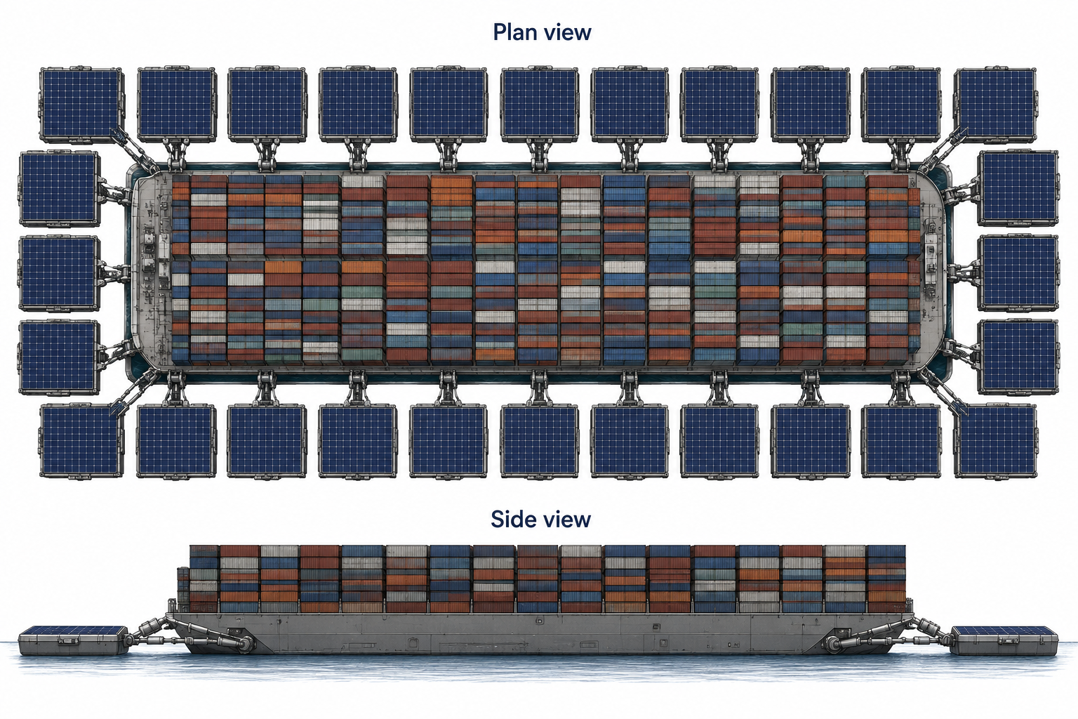
Large flows of freight already travel between major trading regions. Sky Clipper would give one such flow a dedicated ocean crossing: a broad, carrier-like hull covered in cargo, surrounded by large square pontoons. Hydraulic connections transfer part of the ship’s load to those pontoons, expanding the flotation area and reducing the central hull’s draft. A shipboard crane travels fore and aft on longitudinal rails, organizing the cargo as warehouse inventory. The entire warehouse moves.
The vessel serves a pair of purpose-built terminals on different continents. Rail, trucks and regional carriers handle the journeys beyond them. It has no reason to enter small harbors, squeeze beneath existing bridges or visit a succession of coastal ports.
That narrow job permits a different object. Its breadth, cargo layout, flotation, power system and loading machinery can be designed together around a repeatable crossing and a repeatable exchange at each end.
Expand the flotation outward
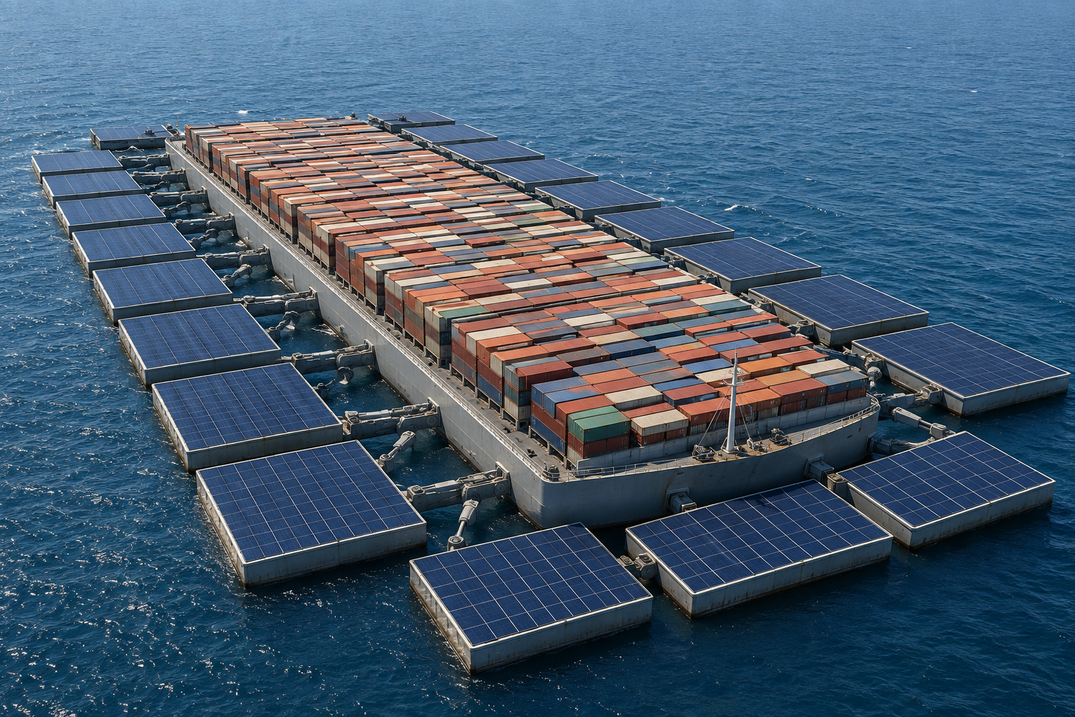
The main hull carries the freight and remains in the water. The square pontoons occupy the surrounding sea surface, with visible gaps and hydraulic linkages between them and the ship. Their buoyancy contributes support through those connections. Their exposed tops provide space for solar panels.
The hull and its perimeter modules therefore form one load-sharing system. Pontoon area, buoyancy reserve and connection forces determine how much weight can be carried outside the main hull. Hydraulic travel and control must accommodate relative movement without allowing destructive loads to pass between modules.
What the architecture changes
Local damage can stay local
Independent cells distribute flotation across the raft. A damaged pontoon need not open the cargo space to the sea or remove the vessel’s entire buoyancy system. The intended response is isolation, redistribution of load and eventual replacement of the affected module.
A missile strike confined to one pontoon is one proposed case for that resilience. It would still remove support and could transmit shock or start a fire. The engineering objective is to preserve the warehouse and its ability to continue after defined local damage; immunity to attack does not follow from separate pontoons alone.
More waterplane, less draft
Sharing weight with the surrounding pontoons lets the main hull sit shallower for the same load. Its broad footprint engages a larger region of the sea, while the hydraulic connections provide a means to manage relative movement between the ship and its perimeter modules.
The aim is a stable freight platform with substantial weather capability. It still experiences wave forces, differential motion and wind loads. Shallow draft alone does not establish clearance over extreme crests or immunity to gales. Experiments on modular floating structures examine the interaction between waves and connected modules.
Freight transfer becomes part of the machine
A travelling ship crane brings containers to one or two transition zones. Suspended railcars on the island’s circular overhead system collect them there and bring outbound freight back to the same zones. The two systems divide terminal circulation from cargo placement aboard each ship.
The purpose is dependable throughput with less dependence on repeated manual handling and individual berth operations. Labor stoppages are one source of interruption; machinery, power and land transport are others. The route needs a dependable operating organization as much as dependable hardware.
Start across the Pacific
Begin with China–United States freight, studying Hong Kong and the Los Angeles region as the first terminal pair. The Port of Los Angeles lists China/Hong Kong as its largest trading partner by cargo value in its 2025 figures. That supports investigating the corridor; it does not establish how much of that trade could fill this service in both directions.
The terminal names identify freight catchments, not approved berths. Hong Kong’s existing terminal network is a starting connection to investigate. Dedicated offshore sites would need their own workable sea conditions, land links and operating arrangements. Nearby alternatives should compete on the total journey rather than the prestige of a port name.
Assemble
Bring a scheduled outbound load into the terminal’s staging system. Assign each container a location before its suspended railcar reaches the ship’s transition zone.
Exchange
Suspended railcars lower freight into one or two transition zones. The ship’s travelling crane places it in the cargo area and retrieves returning freight for collection.
Cross
The warehouse travels its intercontinental route. The cargo remains secured for the passage; berth machinery is stowed for sea.
Dispatch and return
The other terminal transfers freight into its land network, services the vessel and loads the return journey. Additional vessels establish the departure cadence.
Expand by adding terminal pairs once a complete route works. The network grows as a set of dependable trunk links, with regional distribution at its edges.
An island built around a circulating rail system
The terminal occupies an artificial island with its own rail yard. Ships enter bays along a series of small quays, beneath a large circular overhead structure carrying multiple rails. Suspended railcars circulate around that system with individual containers, serving several ships and connecting their freight to the yard and onward movement toward the mainland.
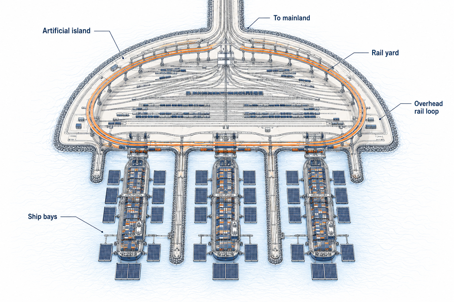
The small quays organize the bays and support the overhead structure. Bay width includes each ship’s surrounding solar pontoons. The overhead rails reach the transition positions on the ships, while the rest of the loop carries containers between bays, staging and the island’s land-transport connections.
The ship places its own cargo
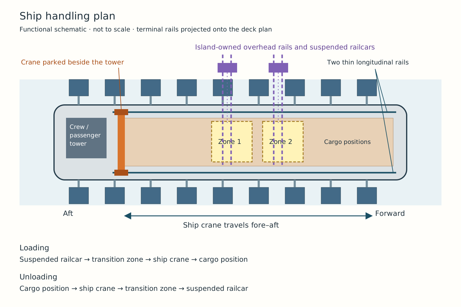
Near the rear of each ship stands a carrier-style tower containing rooms for the crew and potentially passengers. Beside it parks a two-legged overhead freight crane. Its legs stand toward the outside of the cargo area on thin longitudinal rails that run through the cargo layout. The crane travels forward and aft to retrieve or place containers.
Loading
A suspended railcar brings a container to a transition zone and lowers it onto the ship. The ship crane collects it, travels along the longitudinal rails and places it in its assigned cargo position.
Unloading
The ship crane retrieves a container and places it in a transition zone. A suspended railcar lifts it away and carries it into the island’s freight system for onward dispatch.
The overhead terminal system only needs to serve those exchange positions. Each ship’s crane handles the rest of its cargo space. A second transition zone could provide a place for the next container while the crane handles another; the timing and clearances determine whether that actually reduces waiting.
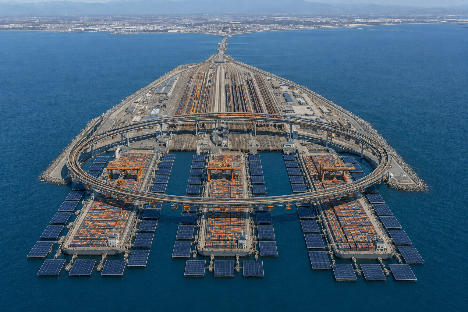
The dedicated island replaces the conventional waterfront handling sequence with an integrated exchange between ship cranes, suspended railcars and rail dispatch. Freight inspection, sorting, storage and maintenance are arranged around that system. Its useful throughput depends on all of them keeping pace.
Automated transfer also changes the labor arrangement that must be negotiated. West Coast terminal automation already exists within collective bargaining: the Pacific Maritime Association describes its contractual history. An offshore terminal does not, by its location alone, settle labor jurisdiction or guarantee uninterrupted operation. The proposal is to build a less interruption-prone freight service, including its staffing, maintenance and labor agreements.
What capacity do the terminal rails provide?
Illustrative capacity of the terminal transfer paths, before accounting for the ship crane and transition zones. “Containers” means physical boxes, not TEU. Assume the same number is unloaded and loaded.
Time = (unloaded boxes + loaded boxes) ÷ (lanes × moves per hour × utilization). This is an idealized terminal-side handling time, not a vessel turnaround prediction. The actual exchange is limited by the slower of the terminal railcars, transition-zone handling, ship crane and onward yard. Mooring, inspection and repair time are additional. Neither lane independence nor this rate has been demonstrated.
Wind, solar and sustained power
A broad platform offers surface area for solar collection and room to investigate wind-assisted propulsion. A fixed corridor makes seasonal winds, weather and energy supply part of the design from the outset. Propulsion, steering, shipboard services and cargo machinery still require a complete power budget.
These options can be compared within one freight architecture without assuming they must all be installed. The winning configuration must supply the crossing reliably and repay its complete costs.
What a wider waterplane buys
In a simplified calm-water calculation, doubling the effective waterplane area halves the mean draft required to support the same mass. The waterplane is the area intersecting the water surface; gaps between the ship and its pontoons do not count.
For illustration, 200,000 tonnes supported by 200,000 m² of vertical-sided waterplane in seawater at 1.025 tonnes/m³ gives about 0.98 metres of draft. If the main hull and perimeter pontoons together provide 400,000 m² at the same total mass, the figure becomes about 0.49 metres.
Those numbers are an idealized comparison, not dimensions or performance assigned to Sky Clipper. Real pontoons, hydraulic machinery and connections add mass. Different hull shapes and module immersion require a full buoyancy and load-sharing calculation. The main hull’s draft depends on the support actually transferred through the links.
The additional flotation must support its own hardware as well as the freight. A complete design must retain capacity for waves, uneven loading and a damaged module while meeting its cargo commitment.
Build the route as a system
Start with a China–US freight commitment and two candidate terminal sites. Establish cargo in each direction, the required departure interval and the land capacity that receives it. Those quantities determine how much warehouse must cross, how often, and how quickly each terminal must turn it around.
Develop the central hull, square pontoon and hydraulic connection together, then test a connected array under waves and loss of support. In parallel, demonstrate the exchange between a suspended railcar, a transition zone and the ship’s travelling crane. Join those results into the smallest working route segment before committing to the full ocean fleet.
The deliverable is a scheduled freight link whose vessel, transfer system and land connections meet one service promise. Once that link works, the same architecture can connect another pair of continents.