A tiny foot.
A steadier placement.
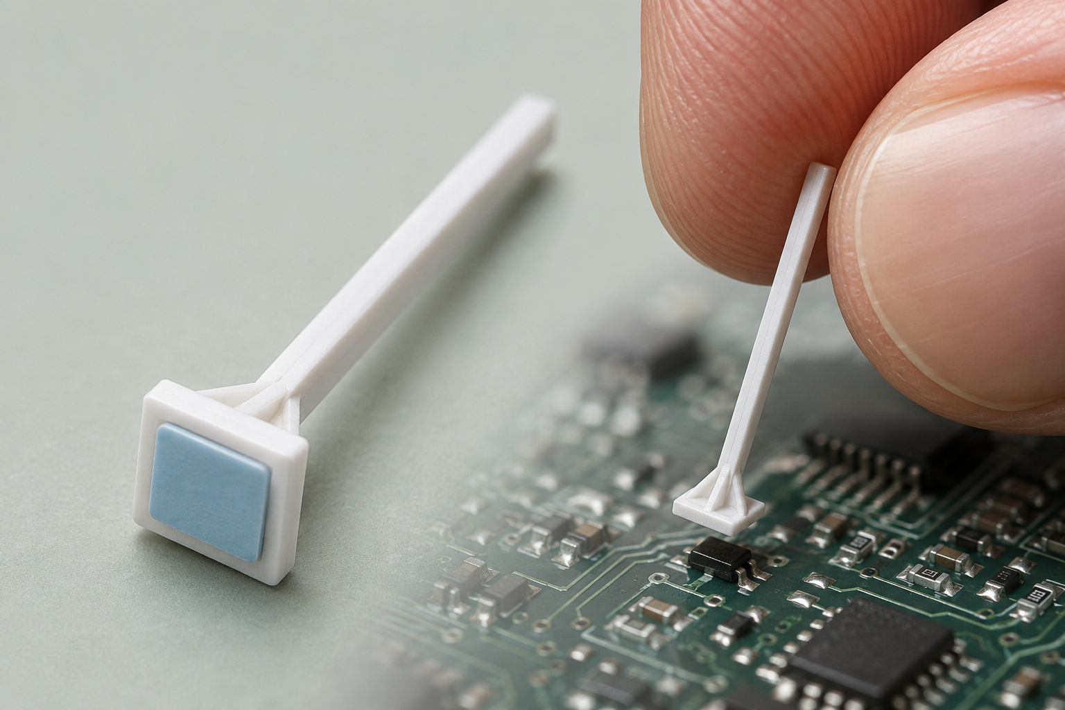
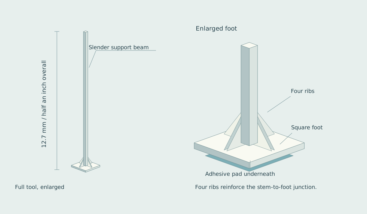
A disposable pick, barely half an inch long, ends in a miniature square foot. Four ribs support the junction with its slender beam. A tiny adhesive pad underneath lifts a chip component without squeezing its sides.
Bring the component down flat.
A loose chip can turn in tweezers or spring away under side pressure. The Micro-Place Pick holds the top instead: touch, lift, align, then set it precisely onto the board. Its short support beam keeps the hand near the work, while the small contact leaves the component’s edges visible.
The shape resembles a miniaturized jack foot. A square plate spreads the support around the stem, and four triangular ridges brace that junction. The adhesive is a separate, smaller patch on the lower face. The plate supports it; the patch performs the pickup.
The whole tool, and the end that matters
Support without a bulky handle
The ridges connect the stem to the foot around four sides. They make the intended load path visible without turning the end into a large ball or a flexible blob. A stiff, cleanly formed junction is useful when a tiny fingertip correction must reach the component as a predictable motion.
The stem remains plain and disposable. There is no squeeze mechanism, vacuum hose or reusable handle to clean. The commercial object could be a sealed strip of short picks, selected by pad footprint and tack.
Contact only where it helps
The adhesive face should stay within the component’s top surface, clear of terminals. A tiny chip needs a correspondingly tiny patch; a universal oversized pad would hide edges and risk touching nearby material.
The drawing specifies a shape, not a qualified polymer or adhesive. Foot stiffness, electrostatic behavior, surface residue and compatibility with the assembly process would determine the useful material choices.
A transfer, rather than a grip contest
| Touch and lift | A small pad makes contact with the top of the chip. It needs enough tack to carry the component through normal hand motion. |
|---|---|
| See and align | The slender support approaches from above. Package edges and board marks remain visible so position and rotation can be corrected. |
| Set and release | The component meets solder paste or another receiving tack. The pick withdraws through a controlled peel, leaving the component in place. |
| Use a fresh tip | A pick that has touched flux, dust or skin oil no longer has a known contact condition. A fresh sealed pick restores the intended starting point. |
The difficult part is letting go.
Strong pickup is easy to imagine. Clean release is the product. The receiving surface must retain the component during withdrawal, and the pad must peel away without shifting it, lifting an edge or disturbing the paste.
A single pull-force number will not describe that transfer. Contact area, surface finish, dwell time, peel angle, withdrawal speed and storage age all affect the result. The useful specification is a reliable pickup-and-release window for a stated component and paste combination.
A few grades, with known behavior
A small family of pad sizes and adhesive grades could cover common loose chip components. Each packet would identify the intended range and storage conditions. Color coding belongs on the packet or stem, away from the contact surface.
Consistency matters more than maximum stickiness. Fibers, strings and residue on a component are failures even when placement looks correct. A clean transfer is part of the definition of success.
Prove it on the same board.
Compare the reinforced-foot picks with tweezers and existing tack tools on matched placement tasks. Record time to correct placement, lost parts, angular error, disturbed paste, neighboring components moved and residue after release. Repeat across package surfaces, paste types and aged sealed samples.
Those observations answer the practical question: does this tiny foot make a few precise placements easier? A repair bench, prototype run or teaching session needs dependable control over a handful of parts. If a short molded stem and a calibrated contact can provide it, the tool can remain pleasantly small.